Laser Seam Tracking System for Welding Automation
Laser Seam Tracking System for Welding Automation RF627Smart-Weld
The Seam Tracking System is designed to be used in robotic welding systems and is intended to automatically control the position of the welding torch during the welding process.
RF627Smart-Weld system structure:
![]()
Main features:
■ direct connection of the scanner to the robot controller without an intermediate computing module;
■ control of the movement of the robot and full cycle of welding process;
■ built-in interfaces to popular robots;
■ ready-made file of various types of welding joints;
■ simple and intuitive building a work algorithm inside scanner WEB-interface using a graph of smart blocks;
■ 3D real-time tracking visualization;
■ the set of scanners of various ranges, optimized for work in welding conditions.
Specification:
| Sampling rate, accuracy, resolution | |
| Nominal sampling rate (full working range) |
484 profiles/s (standard mode), 938 profiles/s (DS mode) |
| Maximum sampling rate (ROI mode) |
4884 profiles/s, 6379 profiles/s (DS mode) |
| Linearity (measurement error), Z axis |
±0.05% of the range (standard mode), ±0.1% of the range (DS mode) |
| Linearity (measurement error), X axis | ±0.2% of the range |
| Resolution, Z axis |
0.01% of the range (standard mode) 0.02% of the range (DS mode) |
| Resolution, X axis | 648 or 1296 points (programmable value) |
| Laser | |
|
660 nm or 450 nm Class 2M according to IEC/EN 60825-1:2014 |
|
| Interface | |
| Basic | Ethernet / 1000 Mbps |
| Synchronization input | RS422, 3 channels |
| Power supply | 9...30 V or 12...36 V for scanners with Blue laser |
| Power consumption, not more | 6 W (without a built-in heater) |
| Environmental resistance | |
| Enclosure rating | IP67 |
| Vibration | 20 g / 10...1000 Hz, 6 hours for each of XYZ axes |
| Shock | 30 g / 6 ms |
| Operating ambient temperature |
-20...+40 or -20...+80 for scanners with built-in air cooling system -20...+150 for scanners with built-in water cooling system |
| Storage temperature °С | -20...+70 |
| Relative humidity | 5-95% (no condensation) |
| Housing/windows material | aluminum/glass |
| Replaceable protective windows | glass |
Working ranges and overall dimensions:
| Range | MR, mm | SMR, mm | Хsmr, mm | Xemr, mm | Dimensions, figure | Weight, kg | Option: air or water cooling, drawing, figure | Option: shutter, figure |
| 65/25-20/22 | 25 | 65 | 20 | 22 | 1 | 0.7 | 2 | 3 |
| 70/50-30/41 | 50 | 70 | 30 | 41 | 1 | 0.7 | 2 | 3 |
| 76/100-48/82 | 100 | 76 | 48 | 82 | 1 | 0.7 | 2 | 3 |
| 70/130-40/86 | 130 | 70 | 40 | 86 | 4 | 0.7 | 4 | 4 |
| 250/130-52/76 | 130 | 250 | 52 | 76 | 5 | 0.9 | 5 | 5 |
| 82/200-60/150 | 200 | 82 | 60 | 150 | 1 | 0.7 | 2 | 3 |
| 90/250-65/180 | 250 | 90 | 65 | 180 | 1 | 0.7 | 2 | 3 |
Overall and mounting dimensions of laser scanners:

Fig.1

Fig.2
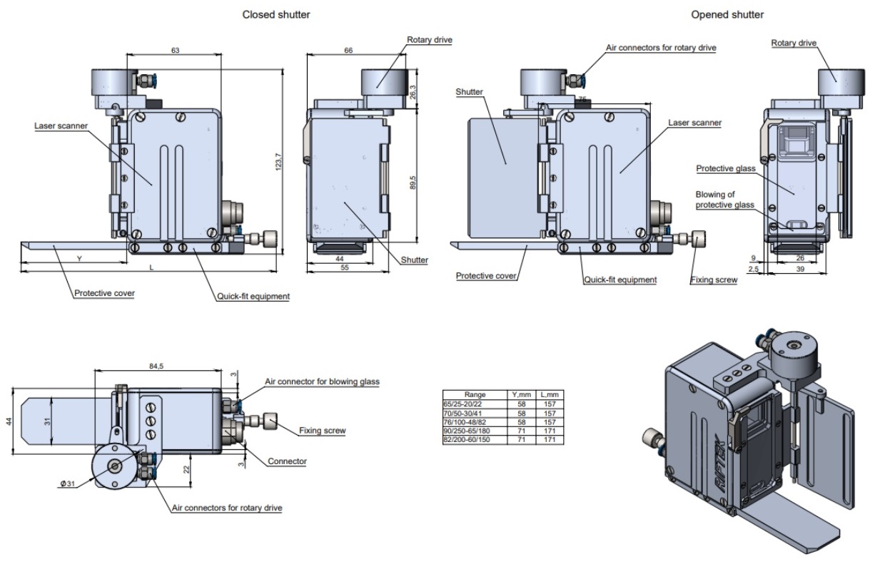
Fig.3
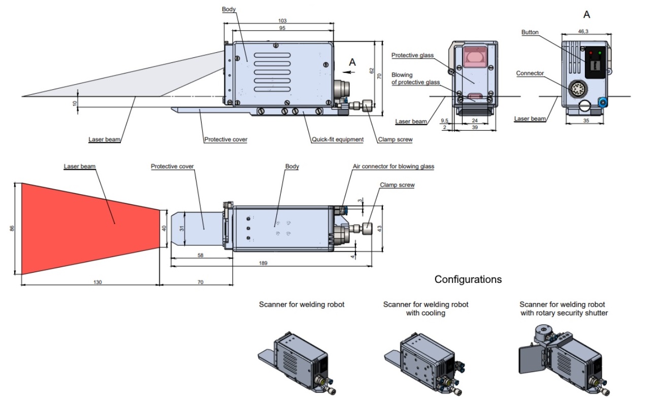
Fig.4

Fig.5
Rugged industrial tablet
The tablet is intended for the initial setup of the system by an engineer and subsequent control of the system operation by the adjuster and the operator of the welding robot.
The pre-installed software is designed to display the graphical interface and manage its settings, taking into account access control (engineer/adjuster/operator).
Since the tablet is for display, configuration and diagnostic purposes only (does not perform any calculations), the user may use other technical means (other types of tablets, personal or industrial computers). In the case of using other technical means, it is necessary to follow the instructions given in the documentation for the RF627Smart scanner.

Fig.6
Technical characteristics:
| Parameter | Value | |
| Architecture | CPU | Intel cherry trail Z8350, 1.44Ghz-1.92GHz |
| OS | Windows 10 pro | |
| RAM/ROM | 4GB+64GB | |
| Display | Size | 10,1" |
| Resolution | 1920x1200 | |
| Touch type | Capacitive | |
| Interfaces | Type-A | USB2.0 x1 |
| Type-А | USB.0 x1 | |
| MicroUSB | x1 | |
| RJ45 Ethernet | 10/100/1000M x1 | |
| DB9 RS232 | 9-pin serial port x1 | |
| DC power interface | DC 12V 2A x1 | |
| Enclosure rating | Degree of protection | Waterproof IP65, but in fact is IP67 design. Drop 1.2m, 6 sides |
| Certification standards | Military 810G. EU CE, US FCC | |
| Operating Temperature | -20°С...60°С | |
| Built-in battery | Battery type | Built-in removable Li-ion Polymer Battery |
| Rated capacity | 10500 mAh | |
| Dimensions | 275х180x20 mm | |
Industrial Ethernet switch
The switch is designed to provide network interaction between the tablet and the 2D scanner, as well as to exchange data with the robot controller.
It is allowed to use a standard network switch included in the welding kit (for example, between the robot and the controller). In this case, make sure the network settings are correct.

Fig.7
Specification:
| Parameter | Value |
| Network ports | 5-RJ45-10/100/Mbps |
| Power supply | 10...60V - 1.1W - 0.045А |
| Operating conditions |
Temperature: -10...60°С Air humidity: 5...95% |
| Enclosure rating | IP40 |
| Dimensions | see Figure 7 |
Protection unit
This unit provides power protection for the 2D laser scanner and includes a quick-change fuse.
PRINCIPLE OF OPERATION
The laser scanner is mounted on the robot flange next to the welding torch in such a way that during the welding process and movement along the welding groove, the scanner is ahead of the welding tool.
The scanner is calibrated to obtain the coordinate transformation matrix. The calibration procedure is described in the User's Manual for RF627Smart: https://riftek.com/upload/iblock/65a/2D_Laser_Scanners_eng.pdf
Using the web interface of the scanner, a computation graph is formed from the library of smart blocks, taking into account the specifics of the equipment, namely the robot type, communication protocol, groove type, geometric parameters of groove templates used to control the position and constraints applied to them, etc. If the supplied file does not contain the required groove template, the user can create a new template himself or with the support of the manufacturer using the provided template editor (see User's Manual for RF627Smart).
The script for controlling the groove tracking block and the welding robot is being configured. The control script provides cyclic execution of the main stages of welding: placing the welding tool in the starting position, moving the tool in the direction of the beginning of the groove (search for the entry point into the groove), bringing the tool to the beginning of the groove and generating signals to external systems (welding controller) about the need for ignition and other actions, stopping the robot movement, transferring the coordinates to the robot for the movement of the tool along the welding groove, bringing the tool to the end of the groove and generating signals to external systems (welding controller) about the need to reduce the current or extinguish the arc (and other actions), bringing the tool to its original position.
During operation, each profile received by the scanner is processed in accordance with the algorithm specified by the graph, and the following steps are performed: detecting the welding groove template in order to determine the exact coordinates in the scanner coordinate system (2D), transforming the coordinates from the scanner coordinate system to the robot coordinate system (3D), forming the trajectory of the tool in the robot coordinate system, transferring the coordinates to the robot for movement to the next position of the trajectory.
Products
Download
Contattaci
Non esitate a contattarci, saremo lieti di soddisfare qualsiasi vostra richiesta di informazione di natura tecnica ed economica,relative alla nostra sensoristica.
Chiedi informazioni